DuraTech’s IME: Dependability Through 4 Quality Tests
“Just how robust is your IME process?”
We hear this question with increasing frequency.
It’s a valid query. In-mold electronics (IME) technology is growing rapidly due to the attributes it offers engineers in designing 3D, smooth, decorative and easily cleaned surfaces with integrated capacitive touch, lighting, haptic feedback and antennas. IME also offers advantages in the reduction of part size, weight, materials consumption and manufacturing complexity, which also contribute to its soaring popularity, says IDTechEx, an independent research organization on emerging technologies.
As with any technology experiencing explosive growth and employing innovations such as the electrical conductivity of inks and epoxies, and printing and molding methods using extremely high temperatures and pressure, not all suppliers are equal to the challenge of guaranteeing stable, viable IME products. How, then, can a customer be confident their IME provider is manufacturing quality parts?
The best approach to is to vet your suppliers and choose relationships with only those who:
- take quality and part performance seriously
- allocate resources to validate IME stability
- generate data that prove part performance
- employ robust Q/A oversight
To demonstrate the thoroughness of DuraTech’s IME manufacturing and testing processes, this paper looks at a recent study we completed to evaluate the header connection of a printed circuit on an IME part we produced for a customer.
The study was prompted when we received notice from the customer about a few unspecified field failures of the IME part in question. The customer was unsure of the cause, so, together, we embarked on a collaborative effort with them to address not just the immediate issue, but to preemptively refine and improve the reliability of our product, proactively problem-solve and reinforce our partnership.
This particular part uses a printed and formed applique using IMD/IME specific decorative and conductive inks and utilizes a molded-in surface mount header that mates up to printed conductive epoxy pads on the applique. This connection is the focus area of our study.
Looking inside DuraTech's IME
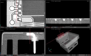
We began with X-Ray and CT scans of returned parts. X-Ray is an excellent, nondestructive diagnostic tool to see inside an opaque IME part. Views into a part are limited, however, as X-Ray produces only two-dimensional images. After the X-Ray examination of the part’s connection between the header foot and the landing pad yielded no definitive results, we invested resources to run a CT scan.
The CT scan offered a three-dimensional picture of the entire part that we then loaded onto computers and cut into 10-micron slices so we could scroll through the entire part. The scan proved, without a doubt, that the connection was intact and robust.

Destructive testing process
With the scans providing no definitive cause for the random part failures, we then designed a comprehensive failure analysis, using nine test groups and one control group. Three of the test groups represented IME parts where epoxy was intentionally underbaked, overbaked, or fully cured. Two other test groups had no epoxy with two or three hits of additional silver on the pads. Another group underwent a four-hour bake to test for possible silver migration into printed ink layers; the final group used non-anisotropic epoxy.
We then used the test groups against the control group to analyze:
- capacitive touch functionality
- resistance (the measure of the opposition to current flow in an electrical circuit)
- potential epoxy migration
- heat and thermo-cycle tolerance
The test groups underwent ohms testing to obtain pre-mold data. The average across six cavities and four loops per cavity measured at 23.9 ohms. Additionally, pre-mold testing of the four-hour bake test group showed no silver migration into the other inks, indicating that the existing production bake schedule was sufficiently driving out the solvent.
Ohms testing was done again after molding. A drop in ohms was expected because of the pressure of injection molding and resin shrink. Of 220 measured traces, the average drop was eight ohms – well within expected limits; none of the molded traces failed, meaning every loop trace was fully connected in all test groups.
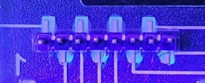
In another test, a 0.1 solution of black light/UV powder was added to one setup of epoxy printing and cured using standard production methods. This was done to test for any migration of the epoxy during injection molding. Tests showed the epoxy did not migrate in the molding process.

A non-anisotropic epoxy was included in the testing program with the theory that if the epoxy was holding as it’s expected to, it could be advantageous to use an epoxy that’s conductive in all directions to better insure a positive connection. Testing showed no advantage or disadvantage to using a non-anisotropic epoxy. However, the theory stands that it could help better connect in every direction, especially knowing that the epoxy doesn’t migrate during injection molding.
Stylus versus test probe analysis
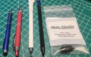
Another round of testing, this time to assess capacitive touch functionality, began with a random stylus, where 26 of 55 parts failed to achieve a delta greater than 100 on various buttons. Failures were random and appeared in each of the nine test groups. The stylus used was a .275” diameter with a very soft durometer.

A second stylus, which was smaller (.230” diameter) with a firmer durometer, was then tested; all parts that were tested with this stylus passed. In fact, the difference in deltas was significant enough that it prompted our team to try testing the part’s capacitive touch functionality with a conductive finger probe. The probe provided the greatest deltas, with every part passing.
Two other stylus types, meant for tablet use, were also tested. While they showed better results than the first two styli, they did not perform better than the conductive simulated finger probe.
Thermal range testing
Our team conducted another testing program to evaluate how the header connection to the applique would stand up to temperature extremes. Selected test parts, along with two parts returned from the customer, underwent thermal ranging – from 0°C (32°F) to 65°C (149°F) and then beyond to 85°C (185°F). The parts tested showed no significant changes in deltas that correlated to temperature. All parts tested – including two that were returned by the customer – passed at all temperature test points.
In addition, selected loop trace parts were heat cycled up to 85°C (185°F), tested, then cooled to -30°C (-22°F), tested, then heated back up to 85°C and tested again. The parts were then cycled through the same three temperature series three more times and then tested at room temperature. All connections remained solid, even after parts were thermo-cycled well above and well below the recommended operating ranges.
DuraTech's IME is the answer
These tests were designed to push the limits of the connection joint of the header to the applique and intended to fail this connection. In other words, we did everything we could think of to destroy the header connection; yet of 110 parts tested, none of the tests conducted failed a single part. Therefore, we were able to determine that the printing, forming and molding processes DuraTech uses to manufacture IME parts are solid and reliable.
Through this project, we deepened our understanding of both the product and the customer’s needs, which enhances our ability to innovate and tailor solutions. It’s a testament to our belief that every challenge is an opportunity to learn and improve together.
Furthermore, our commitment to quality and customer satisfaction prompts us to open a second project to explore how circuit design could be involved in the small failure rate our customer is experiencing. This added, extensive research and development pledge is unparalleled in the industry and allows our customers to rest assured that they are in good hands with DuraTech’s IME processes.